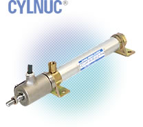
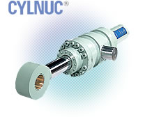
Heavy Duty Smart Linear Position Sensing Cylinder CYLNUC®
Description
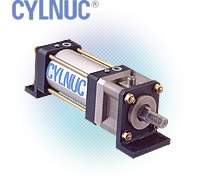
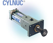
CYLNUC is NSD smart and heavy duty cylinder linear position sensing cylinder that indicates the amount of linear travel and rod extension throughout the range of sensing stroke.
![]()
Hydraulic type SCHH / Pneumatic type SCAH
Ex.
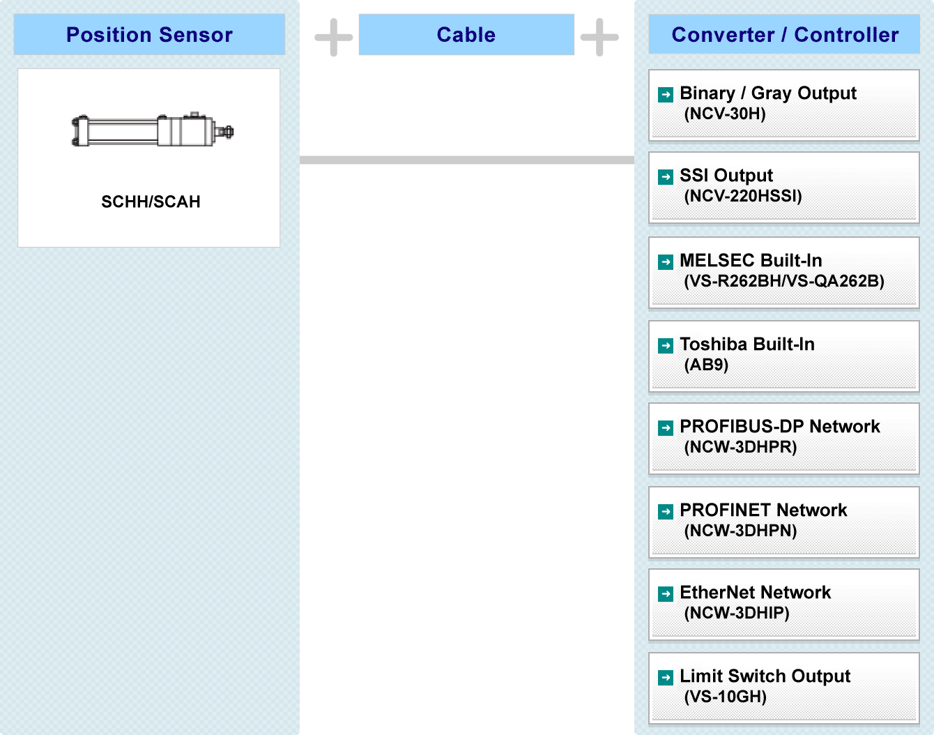
System Configuration
Specification
Cylinder
| Item | Specification | |||||
|---|---|---|---|---|---|---|
| Bore size (mm) | φ40 | φ50 | φ63 | φ80 | φ100 | |
| Rod dia. (mm) | φ18 | φ20 | φ20.4 | φ28 | φ36 | |
| Stroke(mm) | Without bellows | 50〜1000 | 50〜1400 | 50〜1600 | 50〜1800 | |
| With bellows | 50〜1400 | 50〜1500 | ||||
| Operating pressure range(MPa) | 0.2〜5.0 | |||||
| Proof test pressure(MPa) | 7.5 | |||||
| Operating fluid | Mineral oil, water-glycol | |||||
| Cylinder speed range(mm/s) | 3〜300 | |||||
| Ambient operating temperature(℃) | 5〜120 | |||||
Applicable sensor
| Item | Specification |
|---|---|
| Absolute detection range(mm) | 12.8 |
| Resolution(μm) | 1.5625 |
| Repeatability(μm) | 10 mim. [Without load] |
| Linearity error(mm) | 0.15 + L/1000 Max. L:stroke |
| Protection rating | IP67(Conforms to JEM 1030 standard) |
| Vibration resistance | 2.0×10² m/s2 {20G} 200Hz up /down 4h, forward/back 2h, conforms to JIS D1601 standard |
| Shock resistance | 4.9×10³ m/s2 {500G} 0.5ms up/down/forward/back 3 times each, conforms to JIS C5026 standard |
Theoretical cylinder thrust values at various operating pressures
| Bore size (mm) |
Cross-sec. area of cylinder (mm2) |
Rod dia. (mm) |
Cross-sec. area of piston rod (mm2) |
Area of piston's rod face (mm2) |
Cylinder thrust (N) | |||||
|---|---|---|---|---|---|---|---|---|---|---|
| 1.0MPa | 2.0MPa | 3.0MPa | 3.5MPa | 5.0MPa | ||||||
| φ40 | 1256 | φ18 | 254 | Push | 1256 | 1256 | 2513 | 3769 | 4398 | 6283 |
| Pull | 1002 | 1002 | 2004 | 3006 | 3507 | 5010 | ||||
| φ50 | 1963 | φ20 | 314 | Push | 1963 | 1963 | 3926 | 5890 | 6872 | 9817 |
| Pull | 1649 | 1649 | 3298 | 4948 | 5772 | 8246 | ||||
| φ63 | 3117 | φ22.4 | 394 | Push | 3117 | 3117 | 6234 | 9351 | 10910 | 15586 |
| Pull | 2723 | 2723 | 5446 | 8169 | 9531 | 13615 | ||||
| φ80 | 5026 | φ28 | 615 | Push | 5026 | 5026 | 10053 | 15079 | 17592 | 25132 |
| Pull | 4410 | 4410 | 8821 | 13232 | 15437 | 22053 | ||||
| φ100 | 7853 | φ36 | 1017 | Push | 7853 | 7853 | 15707 | 23561 | 27488 | 39269 |
| Pull | 6836 | 6836 | 13672 | 20508 | 23926 | 34180 | ||||
Mass
| Bore size (mm) |
Basic mass (ZERO stroke) (kg) |
Stroke mass per 10 mm (kg) |
Additional mass depending on mounting format (kg) | |||||||
|---|---|---|---|---|---|---|---|---|---|---|
| OO | LB | FA | FB | CA | CB | TA | TC | |||
| φ40 | 3.2 | 0.09 | 0 | 0.51 | 0.31 | 0.31 | 0.43 | 0.50 | 0.27 | 0.42 |
| φ50 | 5.0 | 0.08 | 0 | 0.92 | 0.45 | 0.45 | 0.62 | 0.89 | 0.41 | 0.73 |
| φ63 | 5.5 | 0.10 | 0 | 1.24 | 0.62 | 0.62 | 0.96 | 1.25 | 0.50 | 0.77 |
| φ80 | 8.8 | 0.19 | 0 | 2.13 | 1.52 | 1.52 | 1.57 | 2.25 | 1.76 | 1.51 |
| φ100 | 12.4 | 0.24 | 0 | 3.44 | 2.51 | 2.51 | 2.44 | 3.36 | 2.90 | 2.69 |

Dimensions
 SCHH-□×□-OO
SCAH-□×□-OO- SCHH-□×□-LB
SCAH-□×□-LB - SCHH-□×□-FA
SCAH-□×□-FA - SCHH-□×□-FB
SCAH-□×□-FB - SCHH-□×□-CA
SCAH-□×□-CA - SCHH-□×□-CB
SCAH-□×□-CB - SCHH-□×□-TA
SCAH-□×□-TA - SCHH-□×□-TC
SCAH-□×□-TC
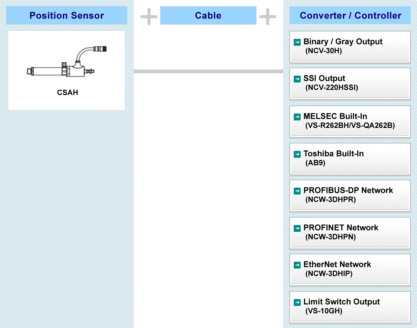
Pneumatic type CSAH
Ex.
| Item | Code | Description | ||
|---|---|---|---|---|
| Bore size | 20 | Φ20 | Units : mm | |
| 40 | Φ40 | |||
| Stroke | 50 ~ 500 | Φ20 | 50 ~ 500 : 50 mm units 600 ~ 700 : 100 mm units |
Units : mm |
| 50 ~ 700 | Φ40 | |||
| Mounting style | [FA]Flange on rod end side |
|||
[LS]Foot on rod end side /parallel to axis  |
||||
[TB]Trunnion on head end side |
||||
[FB]Flange on head end side |
||||
[LB]Foot both ends /parallel to axis  |
||||
| Max. operating pressure | 7 | 0.7 MPa(7kgf/cm2) | ||
| 0 | Piston with hole | |||
| Connector | B | With connector(NJW-2012-PM) | ||
| R | Crimp-type terminal(R1.25-4) | |||
| Cable length | 2.0 | 2 m | ||
Option |
A1 | Lock nut (accessory) | ||
| A2 | Clevis / single | |||
| A3 | Clevis / double (supplied with a Pivot pin A4) | |||
| A4 | Pivot pin (for Clevis) | |||
| C5 | Bellows | |||
System Configuration
Specification
Cylinder
| Item | Specification | ||
|---|---|---|---|
| Bore size (mm) | φ20 | φ40 | |
| Rod dia. (mm) | φ10 | φ14 | |
| Stroke(mm) | Without bellows | 50〜500 | 50〜700 |
| With bellows | |||
| Operating pressure range(MPa) | 0.1〜0.7 | ||
| Proof test pressure(MPa) | 1.05 | ||
| Operating fluid | Compressed air | ||
| Cylinder speed range(mm/s) | 50〜500 | ||
| Ambient operating temperature(℃) | 5〜120 | ||
Applicable sensor
| Item | Specification |
|---|---|
| Absolute detection range(mm) | 12.8 |
| Resolution(μm) | 1.5625 |
| Repeatability(μm) | 10 mim. [Without load] |
| Linearity error(mm) | 0.25 + L/2000 Max. L:stroke |
| Protection rating | IP67(Conforms to JEM 1030 standard) |
| Vibration resistance | 2.0×10² m/s2 {20G} 200Hz up /down 4h, forward/back 2h, conforms to JIS D1601 standard |
| Shock resistance | 4.9×10³ m/s2 {500G} 0.5ms up/down/forward/back 3 times each, conforms to JIS C5026 standard |
Theoretical cylinder thrust values at various operating pressures
| Bore size (mm) |
Cross-sec. area of cylinder (mm2) |
Rod dia. (mm) |
Cross-sec. area of piston rod (mm2) |
Area of piston's rod face (mm2) |
Cylinder thrust (N) | ||||||
|---|---|---|---|---|---|---|---|---|---|---|---|
| 0.2MPa | 0.3MPa | 0.4MPa | 0.5MPa | 0.6MPa | 0.7MPa | ||||||
| φ20 | 314 | φ10 | 78 | Push | 314 | 62 | 94 | 125 | 157 | 188 | 219 |
| Pull | 235 | 47 | 70 | 94 | 117 | 141 | 164 | ||||
| φ40 | 1256 | φ14 | 153 | Push | 1256 | 251 | 376 | 502 | 628 | 753 | 879 |
| Pull | 1102 | 220 | 330 | 441 | 551 | 661 | 771 | ||||
Mass
| Bore size (mm) |
Basic mass (ZERO stroke) (kg) |
Stroke mass per 10 mm (kg) |
Additional mass depending on mounting format (kg) | ||||
|---|---|---|---|---|---|---|---|
| FA | FB | LB | LS | TB | |||
| φ20 | 1.2 | 0.01 | 0.06 | 0.06 | 0.15 | 0.08 | 0.10 |
| φ40 | 1.5 | 0.02 | 0.15 | 0.15 | 0.26 | 0.13 | 0.20 |
Dimensions
- CSAH-20×□-FA
CSAH-40×□-FA - CSAH-20×□-LS
CSAH-40×□-LS - CSAH-20×□-TB
CSAH-40×□-TB - CSAH-20×□-FB
CSAH-40×□-FB - CSAH-20×□-LB
CSAH-40×□-LB
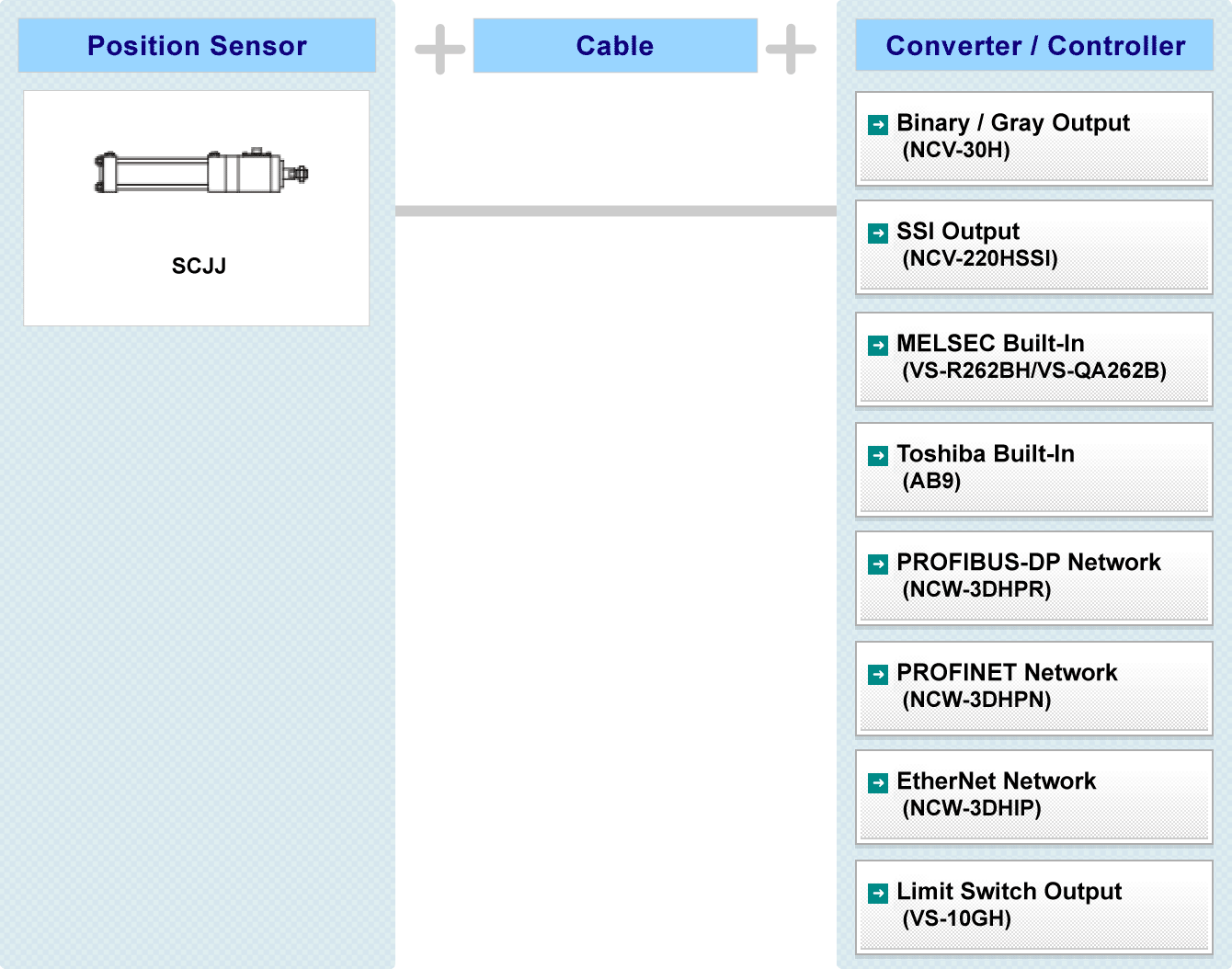
Hydraulic type SCJJ
Ex.
| Item | Code | Description | ||||||||||||
|---|---|---|---|---|---|---|---|---|---|---|---|---|---|---|
| Operating fluid | F | Specify only if phosphate ester is required. | ||||||||||||
| Bore size (mm) | 40~160 | 40 | 50 | 63 | 80 | 100 | 125 | 140 | 160 | |||||
| Rod dia. (mm) | B | 22 | 28 | 36 | 45 | 56 | 70 | 80 | 90 | |||||
| Stroke(mm) | With bellows: 50~300 Without bellows: 50~400 |
Bore size:40 | 50~500:50 units 600~1000:100 units 1200~1600:200 units |
|||||||||||
| 50~1200 | Bore size:50 | |||||||||||||
| 50~1600 | Bore size: 63, 80, 100,125,140,160 |
|||||||||||||
| Mounting style | [LA] | Foot/Side Lugs |
||||||||||||
| [LB] | Foot both ends /parallel to axis |
|||||||||||||
| [FD] | Flange on head end side |
|||||||||||||
| [FY] | Flange on rod end side |
|||||||||||||
| [CA] | Clevis / single |
|||||||||||||
| [CB] | Clevis / double |
|||||||||||||
| [TA] | Trunnion on Rod End Side |
|||||||||||||
| [TC] | Intermediate Fixed Trunnion |
|||||||||||||
| Maximum operating pressure | 70 | 7 MPa(70kgf/cm2) | ||||||||||||
| 140 | 14 MPa(140kgf/cm2) | |||||||||||||
| Cushion | B | Both ends of cylinder | ||||||||||||
| R | Pull | |||||||||||||
| H | Push | |||||||||||||
| N | None | |||||||||||||
| Cushion valve location *1 | A |  |
||||||||||||
| B | ||||||||||||||
| C | ||||||||||||||
| D | ||||||||||||||
| N | None | |||||||||||||
| Option | E | Long rod end | ||||||||||||
| F | Bellows, nylon tarpaulin 80℃ max. | |||||||||||||
| G | Bellows, neoprene 130℃ max. | |||||||||||||
| H | Bellows, silicone glass 250℃ max. | |||||||||||||
| (E) K *2 | Lock nut | |||||||||||||
| L | Clevis / single | |||||||||||||
| M | Clevis / double | |||||||||||||
| Connector | D | Connector (NJW-2012-RM) + no cable | ||||||||||||
| B | Connector (NJW-2012-PM) + robotic cable | |||||||||||||
| Z | No connector + robotic cable | |||||||||||||
| BH | Connector (NJW-2012-PM) + heat-resistant cable | |||||||||||||
| ZH | No connector + heat-resistant cable | |||||||||||||
| Cable length | 2 | 2m | ||||||||||||
| 5 | 5m | |||||||||||||
| 10 | 10m | |||||||||||||
| Port location *1 Air-breede location Cable location *3 Drain port location *3 |
A | |
||||||||||||
| B | ||||||||||||||
| C | ||||||||||||||
| D | ||||||||||||||
*1: The port and the cushion valvecannot be mounted facing in the same location.
*2: If a lock nut (K) is to be mounted at the rod end, the "long rod end style" item (E) must be selected.
*3: The cable and the drain port cannot be mounted facing in the same location.
System Configuration
Specification
Cylinder
| Item | Specification | ||||||||
|---|---|---|---|---|---|---|---|---|---|
| Bore size (mm) | φ40 | φ50 | φ63 | φ80 | φ100 | φ125 | φ140 | φ160 | |
| Rod dia. (mm) | φ22 | φ28 | φ36 | φ45 | φ56 | φ70 | φ80 | φ90 | |
| Maximum stroke length(mm) | Without bellows | 400 | 1200 | 1600 | |||||
| With bellows | 300 | ||||||||
| Maximum operating pressure(MPa) | 14 | ||||||||
| Proof test pressure(MPa) | 21 | ||||||||
| Operating fluid | Mineral oil, water-glycol, polyol ester, phosphate ester, water-in-oil emulsion |
||||||||
| Cylinder speed range(mm/s) | 10〜400 | 10〜300 | 10〜200 | ||||||
| Ambient operating temperature(℃) | 5〜80 | ||||||||
Applicable sensor
| Item | Specification |
|---|---|
| Absolute detection range(mm) | 12.8 |
| Resolution(μm) | 1.5625 |
| Repeatability(μm) | 10 mim. [Without load] |
| Linearity error(mm) | 0.15 + L/5000 Max. L:stroke |
| Temperature drift | t {0.0016 + ( L × 1.17 × 10⁻⁵) } t:Temperature variation(℃) L:stroke |
| Protection rating | IP67(Conforms to JEM 1030 standard) |
| Vibration resistance | 2.0×10² m/s2 {20G} 200Hz up /down 4h, forward/back 2h, conforms to JIS D1601 standard |
| Shock resistance | 4.9×10³ m/s2 {500G} 0.5ms up/down/forward/back 3 times each, conforms to JIS C5026 standard |
Theoretical cylinder thrust values at various operating pressures
| Bore size (mm) |
Cross-sec. area of cylinder (mm2) |
Rod dia. (mm) |
Cross-sec. area of piston rod (mm2) |
Area of piston's rod face (mm2) |
Cylinder thrust (kN) | ||
|---|---|---|---|---|---|---|---|
| 7MPa | 14MPa | ||||||
| φ40 | 1256 | φ22 | 380 | Push | 1256 | 8.79 | 17.59 |
| Pull | 876 | 6.13 | 12.27 | ||||
| φ50 | 1963 | φ28 | 615 | Push | 1963 | 13.74 | 27.48 | Pull | 1347 | 9.43 | 18.86 |
| φ63 | 3117 | φ36 | 1017 | Push | 3117 | 21.82 | 43.64 |
| Pull | 2099 | 14.69 | 29.39 | ||||
| φ80 | 5026 | φ45 | 1590 | Push | 5026 | 35.18 | 70.37 |
| Pull | 3436 | 24.05 | 48.10 | ||||
| φ100 | 7853 | φ56 | 2463 | Push | 7853 | 54.97 | 109.95 |
| Pull | 5390 | 37.73 | 75.47 | ||||
| φ125 | 12271 | φ70 | 3848 | Push | 12271 | 85.90 | 171.80 |
| Pull | 8423 | 58.96 | 117.92 | ||||
| φ140 | 15393 | φ80 | 5026 | Push | 15393 | 107.75 | 215.51 |
| Pull | 10367 | 72.57 | 145.14 | ||||
| φ160 | 20106 | φ90 | 6361 | Push | 20106 | 140.74 | 281.48 |
| Pull | 13744 | 96.21 | 192.42 | ||||
Mass
| Bore size (mm) |
Rod dia. (mm) |
Stroke mass per 100 mm (kg) |
Additional mass depending on mounting format (kg) | |||||||
|---|---|---|---|---|---|---|---|---|---|---|
| LA | LB | FY | FD | CA | CB | TA | TC | |||
| φ40 | 22 | 0.9 | 7.8 | 7.9 | 7.81 | 8.4 | 8.03 | 8.1 | 7.5 | 8.0 |
| φ50 | 28 | 1.3 | 13.1 | 13.1 | 13.3 | 14.3 | 13.3 | 13.5 | 12.4 | 13.3 |
| φ63 | 36 | 1.9 | 18.5 | 19.2 | 18.9 | 20.6 | 19.8 | 20.5 | 18.0 | 19.4 |
| φ80 | 45 | 2.9 | 26.8 | 28.1 | 28.0 | 30.6 | 28.8 | 29.7 | 26.4 | 28.2 |
| φ100 | 56 | 4.4 | 44.4 | 46.5 | 46.6 | 50.7 | 48.8 | 50.3 | 44.0 | 47.9 |
| φ125 | 70 | 7.8 | 76.1 | 83.1 | 79.7 | 86.6 | 84.0 | 87.0 | 74.6 | 81.1 |
| φ140 | 80 | 10.4 | 99.1 | 109.1 | 104.0 | 122.6 | 111.2 | 117.3 | 98.0 | 106.8 |
| φ160 | 90 | 12.5 | 136.9 | 149.5 | 143.3 | 158.5 | 155.2 | 164.1 | 135.0 | 149.0 |
Dimensions
- SCJJ□B□-LA
- SCJJ□B□-LB
- SCJJ□B□-FD
- SCJJ□B□-FY
- SCJJ□B□-CA
- SCJJ□B□-CB
- SCJJ□B□-TA
- SCJJ□B□-TC
Hydraulic MILL type SCM
Hydraulic JIS type SCJ
Ex.
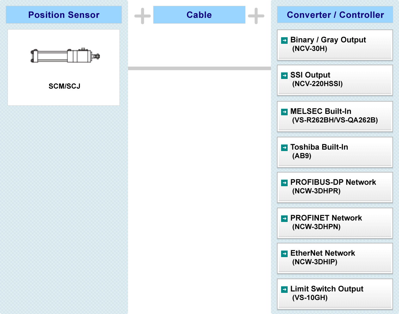
System Configuration
Specification
Cylinder
| Item | Specification | ||||||||||||
|---|---|---|---|---|---|---|---|---|---|---|---|---|---|
| Bore size (mm) | φ40 | φ50 | φ63 | φ80 | φ100 | φ125 | φ140 | φ160 | φ180 | φ200 | φ220 | φ250 | φ320 |
| Rod dia. (mm) | φ22.4 φ28 |
φ22.4 φ28 φ36 |
φ28 φ36 φ45 |
φ36 φ45 φ56 |
φ45 φ56 φ70 |
φ56 φ70 φ90 |
φ63 φ80 φ100 |
φ70 φ90 φ110 |
φ80 φ100 φ125 |
φ90 φ110 φ140 |
φ100 φ125 φ160 |
φ110 φ140 φ180 |
φ160 φ180 |
| Maximum stroke length(mm) | 1200 | 1600 | 2000 | ||||||||||
| Maximum operating pressure(MPa) | SCM:25 SCJ:21 | ||||||||||||
| Proof test pressure(MPa) | SCM:37.5 SCJ:31.5 | ||||||||||||
| Operating fluid | Mineral oil, water-glycol, polyol ester, phosphate ester, water-in-oil emulsion | ||||||||||||
| Cylinder speed range(mm/s) | 5〜500 | ||||||||||||
| Ambient operating temperature(℃) | 5〜120 | ||||||||||||
Applicable sensor
| Item | Specification |
|---|---|
| Absolute detection range(mm) | 12.8 |
| Resolution(μm) | 1.5625 |
| Repeatability(μm) | 10 mim. [Without load] |
| Linearity error(mm) | 0.15 + L/5000 Max. L:stroke |
| Protection rating | IP67(Conforms to JEM 1030 standard) |
| Vibration resistance | 2.0×10² m/s2 {20G} 200Hz up /down 4h, forward/back 2h, conforms to JIS D1601 standard |
| Shock resistance | 4.9×10³ m/s2 {500G} 0.5ms up/down/forward/back 3 times each, conforms to JIS C5026 standard |
Theoretical cylinder thrust values at various operating pressures
| Bore size (mm) |
Cross-sec. area of cylinder (mm2) |
Rod dia. (mm) |
Cross-sec. area of piston rod (mm2) |
Area of piston's rod face (mm2) |
Cylinder thrust (kN) | ||||
|---|---|---|---|---|---|---|---|---|---|
| 7MPa | 14MPa | 21MPa | 25MPa | ||||||
| φ40 | 1256 | φ22.4 (B) φ28 (A) |
394 615 |
Push | 1256 | 8.79 | 17.59 | 26.38 | 31.41 |
| Pull | 862 640 |
6.03 4.48 |
12.07 8.97 |
18.11 13.45 |
21.56 16.02 |
||||
| φ50 | 1963 | φ22.4 (C) φ28 (B) φ36 (A) |
394 615 1017 |
Push | 1963 | 13.74 | 27.48 | 41.23 | 49.08 | Pull | 1569 1347 945 |
10.98 9.43 6.61 |
21.97 18.86 13.23 |
32.95 28.30 19.95 |
39.23 33.69 23.64 |
| φ63 | 3117 | φ28 (C) φ36 (B) φ45 (A) |
615 1017 1590 |
Push | 3117 | 21.82 | 43.64 | 65.46 | 77.93 |
| Pull | 2501 2099 1526 |
17.51 14.69 10.68 |
35.02 29.39 21.37 |
52.53 44.08 32.06 |
62.53 52.48 38.17 |
||||
| φ80 | 5026 | φ36 (C) φ45 (B) φ56 (A) |
1017 1590 2463 |
Push | 5026 | 35.18 | 70.37 | 105.55 | 125.66 |
| Pull | 4008 3436 2563 |
28.06 24.05 17.94 |
56.12 48.10 35.88 |
84.18 72.15 53.83 |
100.21 85.90 64.08 |
||||
| φ100 | 7853 | φ45 (C) φ56 (B) φ70 (A) |
1590 2463 3848 |
Push | 7853 | 54.97 | 109.95 | 164.93 | 196.34 |
| Pull | 6263 5390 4005 |
43.84 37.73 28.03 |
87.68 75.47 56.07 |
131.53 113.21 84.11 |
156.58 134.77 100.13 |
||||
| φ125 | 12271 | φ56 (C) φ70 (B) φ90 (A) |
2463 3848 6361 |
Push | 12271 | 85.90 | 171.80 | 257.70 | 306.79 |
| Pull | 9808 8423 5910 |
68.66 58.96 41.37 |
137.32 117.92 82.74 |
205.98 176.89 124.11 |
245.22 210.58 147.75 |
||||
| φ140 | 15393 | φ63 (C) φ80 (B) φ100 (A) |
3117 5026 7853 |
Push | 15393 | 107.75 | 215.51 | 323.23 | 384.84 |
| Pull | 12276 10367 7539 |
85.93 72.57 52.77 |
171.87 145.14 105.55 |
257.80 217.71 158.33 |
306.91 259.18 188.49 |
||||
| φ160 | 20106 | φ70 (C) φ90 (B) φ110 (A) |
3848 6361 9503 |
Push | 20106 | 140.74 | 281.48 | 422.23 | 502.65 |
| Pull | 16257 13744 10602 |
113.80 96.21 74.22 |
227.60 192.42 148.44 |
341.41 288.63 222.66 |
406.44 343.61 265.07 |
||||
| φ180 | 25446 | φ80 (C) φ100 (B) φ125 (A) |
5026 7853 12271 |
Push | 25446 | 178.12 | 356.25 | 534.38 | 636.17 |
| Pull | 20420 17592 13175 |
142.94 123.15 92.22 |
285.88 246.30 184.45 |
428.82 369.45 276.67 |
510.50 439.82 329.37 |
||||
| φ200 | 31415 | φ90 (C) φ100 (B) φ140 (A) |
6361 9503 15393 |
Push | 31415 | 219.91 | 439.82 | 659.73 | 785.39 |
| Pull | 25054 21912 16022 |
175.37 153.38 112.15 |
350.75 306.77 224.30 |
526.13 460.16 336.46 |
626.35 547.81 400.55 |
||||
| φ220 | 38013 | φ100 (C) φ125 (B) φ160 (A) |
7853 12271 20106 |
Push | 38013 | 266.09 | 532.18 | 798.27 | 950.33 |
| Pull | 30159 25741 17907 |
211.11 180.18 125.34 |
422.23 360.37 250.69 |
633.34 540.56 376.04 |
753.98 643.53 447.67 |
||||
| φ250 | 49087 | φ110 (C) φ140 (B) φ180 (A) |
9503 15393 25446 |
Push | 49087 | 343.61 | 687.22 | 1030.83 | 1227.18 |
| Pull | 39584 33693 23640 |
277.08 235.85 165.48 |
554.17 471.71 330.96 |
831.26 707.56 496.45 |
989.60 842.33 591.01 |
||||
Dimensions
- SCM Basic Type
- SCJ Basic Type
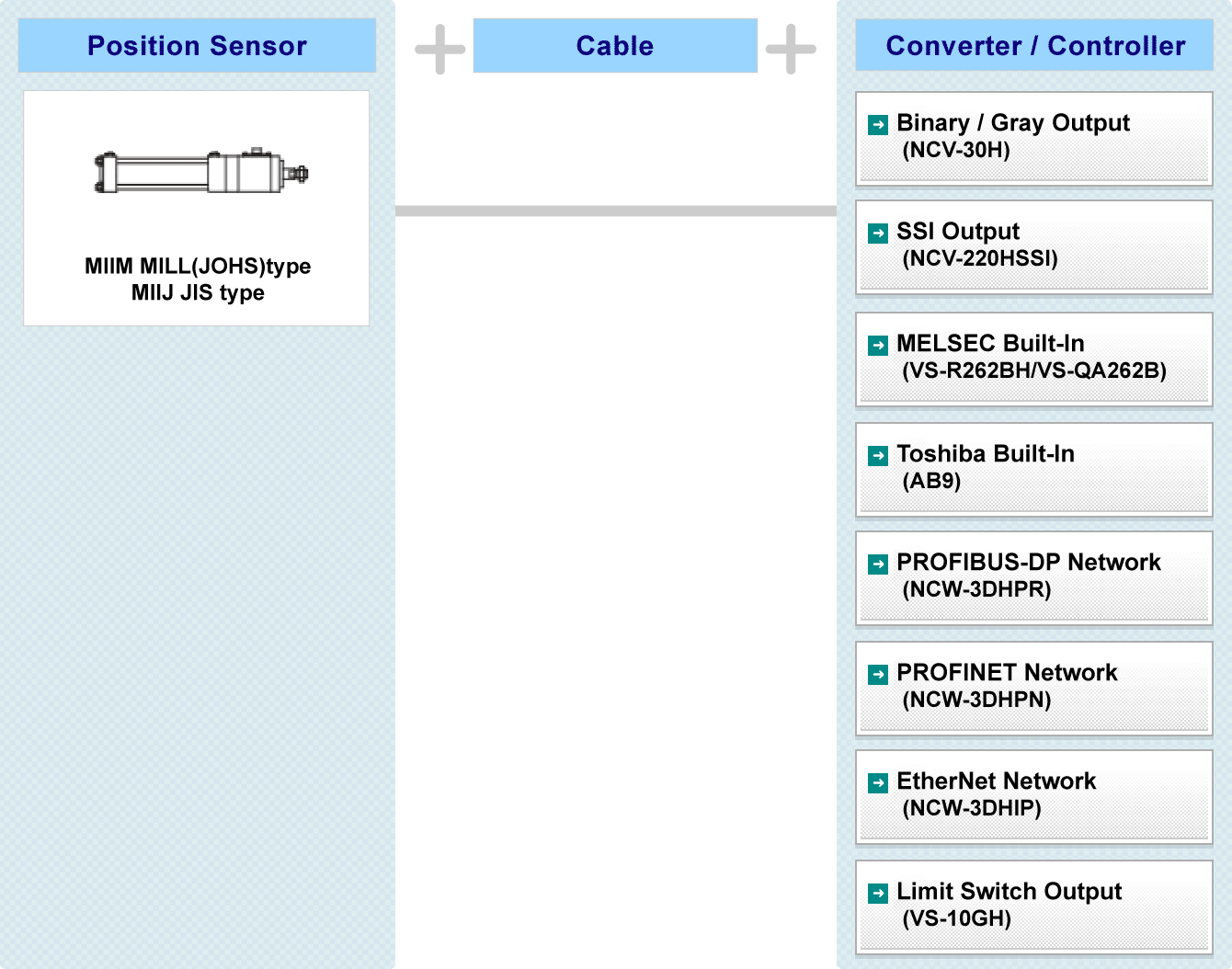
Hydraulic Cylinder built-in inrodsebsor CYLNUC MarkII MILL type MIIM
Hydraulic Cylinder built-in inrodsebsor CYLNUC MarkII JIS type MIIJ
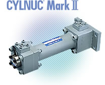
Ex.
| Item | Code | Description | |||||
|---|---|---|---|---|---|---|---|
| Operating fluid | F | Specify only if phosphate ester is required. | |||||
| Cylinder type | J | JIS type | |||||
| M | MILL(JHOS) type | ||||||
| Bore size (mm) | 63~160 | 63 | 80 | 100 | 125 | 140 | 160 *1 |
| Rod dia. (mm) | A | 45 | 56 | 70 | 90 | 100 | 110 |
| B | 36 | 45 | 56 | 70 | 80 | 90 | |
| C | - | 36 | 45 | 56 | 63 | 70 | |
| Stroke(mm) | 50~800 | Rod diameter: less than 50 | 50~500:50 units 600~1000:100 units 1200~1600:200 units |
||||
| 50~1600 | Rod diameter: 50 or more | ||||||
| Mounting style | [LA] | Foot/Side Lugs |
|||||
| [FA] | Flange on rod end side |
||||||
| [TA] | Trunnion on Rod End Side |
||||||
| [TC] | Intermediate Fixed Trunnion |
||||||
| Maximum operating pressure | 70 | 7 MPa(70kgf/cm2) | |||||
| 140 | 14 MPa(140kgf/cm2) | ||||||
| 210 | 21 MPa(210kgf/cm2) | ||||||
| 250 | 25 MPa(250kgf/cm2) ※Only rod diameter 50 or more | ||||||
| Cushion | B | Both ends of cylinder | |||||
| R | Pull | ||||||
| H | Push | ||||||
| N | None | ||||||
| Cushion valve location *2 | A | |
|||||
| B | |||||||
| C | |||||||
| D | |||||||
| N | None | ||||||
| Option | E | Long rod end | |||||
| G | Bellows, neoprene 130℃ max. | ||||||
| H | Bellows, silicone glass 250℃ max. | ||||||
| (E) K *3 | Lock nut | ||||||
| L | Clevis / single | ||||||
| M | Clevis / double | ||||||
| Connector | B | NSD standard connector (NJW-2012-PM) | |||||
| P | Large type connector for KPEV-S cable (NWPC-4012-Ad12) | ||||||
| R | Crimp-type terminal (R1.25-4) | ||||||
| Z | No connector | ||||||
| Cable length | 5 | 5m | |||||
| 10 | 10m | ||||||
| 20 | 20m | ||||||
| Port location *2 Air-breede location Cable location |
A | |
|||||
| B | |||||||
| C | |||||||
| D | |||||||
*1: MIIM only
*2: The port and the cushion valve cannot be mounted facing in the same location.
*3: If a lock nut (K) is to be mounted at the rod end, the "long rod end style" item (E) must be selected.
System Configuration
Specification
Cylinder
| 項目 | Specification | |
|---|---|---|
| Bore size (mm) | φ50 or more | φ80 or more |
| Rod dia. (mm) | φ36 or more | φ50 or more |
| Maximum stroke length(mm) | 800 | 1600 |
| Maximum operating pressure(MPa) | MIIJ:21 MIIM:25 | |
| Proof test pressure(MPa) | 31.5 | 37.5 |
| Operating fluid | Mineral oil, water-glycol, polyol ester, phosphate ester, water-in-oil emulsion |
|
| Cylinder speed range(mm/s) | 8〜500 | |
| Ambient operating temperature(℃) | 5〜120 | |
Applicable sensor
| Item | Specification | ||||||
|---|---|---|---|---|---|---|---|
| Converter model | IRS-51.2P18 | IRS-51.2P30 | |||||
| Absolute detection range(mm) | 51.2 | ||||||
| Resolution(μm) | 6.25 | ||||||
| Repeatability(μm) | 10 mim. [Without load] | ||||||
| Linearity error(mm) | 0.15 + L/5000 Max. L:stroke | ||||||
| Temperature drift | Head (mm/℃) | 0.003 | |||||
| Scale(mm/℃) | 17.3 × 10⁻⁶ | ||||||
| Protection rating | IP67(Conforms to JEM 1030 standard) | ||||||
| Stroke(mm) | 512 | 800 | 768 | 896 | 1152 | 1600 | |
| Vibration resistance | Thrust(m/S2) | 2.0×10² {20G} *1 | |||||
| Radial(m/S2) | 2.0×10² {20G} *1 | 6.9×10 {7G} *1 | 2.0×10² {20G} *1 | 1.5×10² {15G} *1 | 9.8×10 {10G} *1 | 2.9×10 {3G} *1 | |
| Shock resistance | Thrust(m/S2) | 4.9×10³ {500G} *2 | |||||
| Radial(m/S2) | 9.8×10² {100G} *2 | 4.9×10² {50G} *2 | 7.8×10² {80G} *2 | 5.9×10² {60G} *2 | 3.9×10² {40G} *2 | 2.0×10² {20G} *2 | |
*1:200Hz, 4h (JIS D1601)
*2:0.5ms 3 times (JIS C5026)
Theoretical cylinder thrust values at various operating pressures
| Bore size (mm) |
Cross-sec. area of cylinder (mm2) |
Rod dia. (mm) |
Cross-sec. area of piston rod (mm2) |
Area of piston's rod face (mm2) |
Cylinder thrust (kN) | ||||
|---|---|---|---|---|---|---|---|---|---|
| 7MPa | 14MPa | 21MPa | 25MPa | ||||||
| φ63 | 3117 | φ36 (B) φ45 (A) |
1017 1590 |
Push | 3117 | 21.82 | 43.64 | 64.46 | 77.93 |
| Pull | 2099 1526 |
14.69 10.68 |
29.39 21.37 |
44.08 32.06 |
52.48 38.17 |
||||
| φ80 | 5026 | φ36 (C) φ45 (B) φ56 (A) |
1017 1590 2463 |
Push | 5026 | 35.18 | 70.37 | 105.55 | 125.66 |
| Pull | 4008 3436 2563 |
28.06 24.05 17.94 |
56.12 48.10 35.88 |
84.18 72.15 53.83 |
100.21 85.90 64.08 |
||||
| φ100 | 7853 | φ45 (C) φ56 (B) φ70 (A) |
1590 2463 3848 |
Push | 7853 | 54.97 | 109.95 | 164.93 | 196.34 |
| Pull | 6263 5390 4005 |
43.84 37.73 28.03 |
87.68 75.47 56.07 |
131.53 113.21 84.11 |
156.58 134.77 100.13 |
||||
| φ125 | 12271 | φ56 (C) φ70 (B) φ90 (A) |
2463 3848 6361 |
Push | 12271 | 85.90 | 171.80 | 257.70 | 306.79 |
| Pull | 9808 8423 5910 |
68.66 58.96 41.37 |
137.32 117.92 82.74 |
205.98 176.89 124.11 |
245.22 210.58 147.75 |
||||
| φ140 | 15393 | φ63 (C) φ80 (B) φ100 (A) |
3117 5026 7853 |
Push | 15393 | 107.75 | 215.51 | 323.26 | 384.84 |
| Pull | 12276 10367 7539 |
85.93 72.57 52.77 |
171.87 145.14 105.55 |
257.80 217.71 158.33 |
306.91 259.18 188.49 |
||||
| φ160 | 20106 | φ70 (C) φ90 (B) φ110 (A) |
3848 6361 9503 |
Push | 20106 | 140.74 | 281.48 | 422.23 | 502.65 |
| Pull | 16257 13744 10602 |
113.80 96.21 74.22 |
227.60 192.42 148.44 |
341.41 288.63 222.66 |
406.44 343.61 265.07 |
||||
Dimensions
- MIIM Basic Type
- MIIJ Basic Type
Application Introduction


- Principle of ABSOCODER
- Full Line-Up of ABSOCODER
- Single Turn Rotary Position Sensor
- Multi Turn Rotary Position Sensor
- Linear Position Sensor
- Smart Linear Position Sensing Cylinder
- ABSOCODER Built-In Sensing Products
- Extension Sensor Cable
- ezABSO® Pulse Series
- ezABSO® Network Series
- Magnetic Proximity Sensor
- Tension Measurement
- Eddy Current Displacement Sensor
- Explosion Proof Solution
- Joint Development Products
- Slip-Ring and Wireless Transfer Device
- Renewal Solution
- Customized NSD Solution
- Parameter Software


 Explore a Career at NSD
- Work With NSD
 Global Network
- NSD is where the customer needs are
 Principle of ABSOCODER
- Please check the creative principle of NSD ABSOCODER
 NSD HISTORY
- Preparation for a better future and for the next generation
 Major Application
- Please check the wide-use ABSOCODER's application
 Extension Sensor Cable
- Please check the extension sensor cable for ABSOCODER
 NSD YouTube Channel
- Please check the NSD official YouTube channel
 ON-LINE EXHIBITION
- Introducing the NSD on-line exhibition
 ON-LINE MEETING
- NSD on-line meeting service page