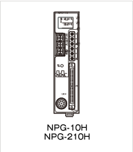
Heavy Duty Pulse Output Converter ABSO PULPUL®
Description

Pulse output smart converter which is connecting with heavy-duty single turn rotary position sensor. User friendly select and adjust the pulse counts according to the system.
Model coding
NPG-[1]10HA[2][3]
- [1]Number of detection axes
-
Code Axis numbers Blank 1(axis) 2 2(axes)
- [2]Pulse output circuit
-
Code Output circuit A Push-pull transistor (complementary output) B Line driver output
- [3]Applicable sensor
-
Code Applicable sensor V1R VRE-P061/074/101 VT VRE-10TP068/101
Note) 1-axis specification is only available for V1R.
ABSOCODER Basic Configuration
Specification
General specification
| Item | Specification |
|---|---|
| Power supply voltage | 24VDC±10% (including ripple) |
| Power consumption | 10W or less |
| Insulation resistance | 20MΩ or more between external DC power terminals and ground (by 500 VDC insulation resistance tester) |
| Withstand voltage | 500 VAC, 60Hz for 1 minute between external DC power terminals and ground |
| Vibration resistance | 20m/s2 10〜500Hz, 10cycles of 5 minutes in 3 directions, conforms to JIS C 0040 standard |
| Ambient operating temperature | 0 ~ +55℃ (No freezing) (Surrounding air temperature rating of 55℃ maximum) |
| Ambient operating humidity | 20 ~ 90 %RH (No condensation) |
| Grounding | Must be securely grounded (ground resistance of 100 ohm or less) |
| Construction | Book-shelf type within enclosure, DIN rail mountable |
| Outside dimension (mm) | 39(W)×155(H)×93(D) Refer to dimensions for details. |
| Mass | Approx. 0.4kg |
Performance Specification
| Item | Specification | ||
|---|---|---|---|
| Converter model | NPG-10HAAV1R NPG-10HABV1R |
NPG-10HAAVT NPG-10HABVT |
NPG-210HAAVT NPG-210HABVT |
| Number of detection axes | 1 | 2 | |
| Number of pulse output channels | 2 channels | 1 channel for each axis | |
| Pulse format | A/B/Z | A/B | |
| Number of pulse | Choice of two pattern from 1 to 1024 |
Choice of two pattern from 10 to 10240 |
10~10240 |
| Resolution | Max. 2048-pulse per revolution | Max. 10240-pulse per revolution | |
| Maximum rotation speed | VRE-P061: 3600 r/min VRE-P074/P101: 4000r/min |
4000r/min | |
| Maximum frequency response of pulse output |
Push-pull output: 200kHz, Line driver output: 300kHz | ||
| Error detection | Sensor disconnected error, low power supply error | ||
| Monitor LED | System ready, various error detection state, function selector switch state, pulse output state, input signal state |
||
| Front panel operation | Error clear | ||
| Input signals | Error clear | ||
| Output signals | System ready, pulse output | ||
Number of divisions, resolution, and sensor cable length of the ABSOCODER sensor
VRE Single-turn type
| Item | Specification | ||||
|---|---|---|---|---|---|
| Converter model | NPG-10HAAV1R NPG-10HABV1R |
NPG-10HAAVT NPG-10HABVT |
NPG-210HAAVT NPG-210HABVT |
||
| Applicable sensor | VRE-P061, VRE-P074, VRE-P101 |
VRE-10TP068, VRE-10TP101 | |||
| Total number of turns | 1 | ||||
| Number of divisions | 8192(213) | 81920 | |||
| Position detection format | Absolute position detection | ||||
| Max. sensor cable length |
Standard(S) | 500m | 300m | ||
| Robotic (RBT) | 250m | 250m | |||
| JKPEV-S (1.25mm2×5P) |
300m | 300m | |||
I/O spcification
Push-pull transistor output
| Item | Specification | |||
|---|---|---|---|---|
| Converter model | NPG-10HAAV1R, NPG-10HAAVT, NPG-210HAAVT | |||
| Input | Input signals | 1ERR CLR, 2ERR CLR (Error clear) *1 | ||
| Input circuit | DC input, photo-coupler isolation | |||
| Rated input voltage | 12VDC/24VDC (10VDC to 30VDC) | |||
| Rated input current | 10mA (24VDC) | |||
| ON voltage | 10VDC or more | |||
| OFF voltage | 4VDC or less | |||
| Output | Output signals | 1POUT1, 1POUT2, 1Z *2 (Channel-1 pulse output) 2POUT1, 2POUT2, 2Z *2 (Channel-2 pulse output) |
1NOR, 2NOR (System ready) *3 | |
| Output circuit | Photo - coupler isolation Push-pull transistor |
Photo - coupler isolation Open collector transistor |
||
| Output logic | Negative logic | Negative logic | ||
| Rated load voltage (Vcc) | 12V/24VDC (10V~30VDC) | 12V/24VDC (10V~30VDC) | ||
| Max. load current | 50mA | 100mA | ||
| Low level output voltage | 2VDC or less | ー | ||
| High level output voltage | VCC-3.5V or more | ー | ||
| Max. voltage drop when ON | ー | 1.5VDC or less | ||
*1: In the case of clearing an error when using the 2-axis type, 1ERR CLR is for 1-axis and 2ERR CLR is for 2-axis.
*2: Z-phrase will be not available if the applicable sensor code is VT.
*3: In the case of using the 2-axis type, the system ready signal is that 1NOR is for 1-axis and 2NOR is for 2-axis.
Line driver output
| Item | Specification | |||
|---|---|---|---|---|
| Converter model | NPG-10HABV1R, NPG-10HABVT, NPG-210HABVT | |||
| Input | Input signals | 1ERR CLR, 2ERR CLR (Error clear) *4 | ||
| Input circuit | DC input, photo-coupler isolation | |||
| Rated input voltage | 12V/24VDC (10V~30VDC) | |||
| Rated input current | 10mA (24VDC) | |||
| ON voltage | 10VDC or more | |||
| OFF voltage | 4VDC or less | |||
| Output | Output signals | 1POUT1, 1POUT2, 1Z *5 (Channel-1 pulse output) 2POUT1, 2POUT2, 2Z *5 (Channel-2 pulse output) |
1NOR, 2NOR (System ready) *6 | |
| Output circuit | Photo-coupler isolation, line driver (equivalent to AM26C31: T.I.) output | |||
*4: In the case of clearing an error when using the 2-axis type, 1ERR CLR is for 1-axis and 2ERR CLR is for 2-axis.
*5: Z-phrase will be not available if the applicable sensor code is VT.
*6: In the case of using the 2-axis type, the system ready signal is that 1NOR is for 1-axis and 2NOR is for 2-axis.


 Explore a Career at NSD
 Global Network


