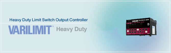
Heavy Duty Limit Switch Output Controller VARILIMIT®
Description
NSD electronic limit switch output controller named VARILIMIT is one of the best well-known controller for the replacement solution of the limit switches. Limit switches, they are used for control a machine, as safety interlocks, or to count objects passing a point. A limit switch is an electromechanical device that consists of an actuator mechanically linked to a set of contacts. When an object comes into contact with the actuator, the device operates the contacts to make or break an electrical connection. Limit switches are used in a variety of applications and environments because of their ruggedness, ease of installation. However, limit switches use mechanical contact to detect the presence or position of an object movement and mechanical contacts should be the one for consumables. Therefore, the operators should maintain this switch at actual mechanical site under harsh environment.
VARILIMIT with ABSOCODER is most of the known solution replacing the existing limit switches. ABSOCODER is installed at mechanical site, and VARILIMIT is installed at control room, and they are connected by extension cable.
VARILIMIT is connecting with multi turn absolute rotary sensor (MRE series) and linear ABSOCODER to measure the absolute position, output limit switch signals and motion control of the system.
Heavy duty VARILIMIT is connecting with heavy duty NSD position sensors under harsh environment.
![]()
![]()
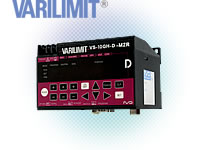
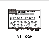
VS-10GH
VS-10GH is multi-function heavy duty VARILIMIT series with limit switch on/off output, position & speed analog voltage output function, multi zero point setting function and motion record function.
- ADVANTAGE
- Model coding
- ABSOCODER Basic Configuration
- Specification
- Dimensions
- Application Introduction
ADVANTAGE
- Max.30 points of limit switch output
- Max.4 points of limit switch on/off angle selected by 1 switch signal
- 1ms of signal updating cycle
- User friendly digital function setting and display
Model coding
VS-10GH-[1]-[2]-[3]
- [1]Output system
-
Code Output A Switch output with position/speed voltage output
(0 ~ 10VDC or -10 ~ +10VDC)C Switch output with position/speed current output (4 ~ 20mA) D Switch output with current position output (BCD or Binray code output) Use the speed voltage and speed current outputs for monitoring.
- [2]Output
-
Code Power supply voltage 1 24VDC
- [3]Applicable sensor
-
Code Applicable sensor V1R VRE-P061/074/101 M2R MRE-32SP061/074/101,MRE-G□SP061/074/101 LC CYLNUC,Inrodsensor(IRS-51.2P)
Contact us about other specifications.
ABSOCODER Basic Configuration

Specification
General specification
| Item | Specification |
|---|---|
| Converter model | VS-10GH-D-1, VS-10GH-A-1, VS-10GH-C-1 |
| Power supply voltage | 24VDC |
| Permissible power voltage range | 21.6 ~ 30VDC |
| Power consumption | 10W or less |
| Insulation resistance | 20MΩ or more between external DC power terminals and ground (by 500 VDC insulation resistance tester) |
| Withstand voltage | 500 VAC, 60Hz for 1 minute between external DC power terminals and ground |
| Vibration resistance | 20m/s2 10〜500Hz, 10cycles of 5 minutes in 3 directions, conforms to JIS C 0040 standard |
| Ambient operating temperature | 0 ~ +55℃ (No freezing) (Surrounding air temperature rating of 55℃ maximum) |
| Ambient operating humidity | 20 ~ 95 %RH (No condensation) |
| Ambient operating environment | Free from corrosive gases and excessive dust |
| Ambient storage temperature | -25〜+70℃ |
| Grounding | Must be securely grounded (ground resistance of 100 ohm or less) |
| Construction | Inside control panel |
| Mounting | Select from two-screw mounting/DIN rail installation/ on-panel mounting using panel mounting fixture VS-K-F. |
| Outside dimension (mm) | 130(W)×81(H)×99(D) |
| Mass | Approx. 0.7kg |
Performance Specification
| Item | Specification |
|---|---|
| Converter model | VS-10GH-D-1, VS-10GH-A-1, VS-10GH-C-1 |
| Number of programs | VS-10B mode:8(1-8) Extended mode:8(1-8) or 32(0-31) |
| Number of switches | 30 |
| Number of multi-dogs | 10 times for each switch output (1-A) (In the case of selecting the VS-10B mode and 8-program in the extended mode) 4 times for each switch output (1-4) (In the case of selecting 32-program in the extended mode) |
| Position data sampling time |
1ms |
| Switch output setting method | Numerical setting from the panel or teaching |
| Min. setting units | Min. : 0.00001 |
| Position setting range | -999999〜999999 |
| Setting value memory | Non-volatile memories (FRAM) |
| Error detection | Sensor power supply error, Sensor data error, Sensor error, Memory error, No setting error, Preset error, Program No. input error, Multi-dog setting error, System error |
| Communication function | Serial (RS-232C) communication (setting value saving or loading, monitoring, operation commands)
|
Auxiliary function lists
| Item | |||||||
|---|---|---|---|---|---|---|---|
| Converter model | VS-10GH-D-1 | VS-10GH-A-1 | VS-10GH-C-1 | ||||
| Operation mode | VS-10B mode |
Extended mode |
VS-10B mode |
Extended mode |
VS-10B mode |
Extended mode |
|
| Existing Functions | Protected switch | ✓ | ✓ | ✓ | ✓ | ✓ | ✓ |
| TEACH setting | ✓ | ✓ | ✓ | ✓ | ✓ | ✓ | |
| Current position output | 6-digit BCD/ 24-bit binary |
- | - | - | - | ||
| Current position preset by travel direction input |
✓ | - | ✓ | - | ✓ | - | |
| Analog voltage output for position | - | - | ✓ | ✓ | - | - | |
| Analog current output for position | - | - | - | - | ✓ | ✓ | |
| New Functions | Current position preset by auto-detecting travel direction |
- | ✓ | - | ✓ | - | ✓ |
| Analog voltage output for speed | - | - | - | ✓ | - | - | |
| Analog current output for speed | - | - | - | - | - | ✓ | |
| Output HOLD | - | ✓ | - | ✓ | - | ✓ | |
| Measuring | - | ✓ | - | ✓ | - | ✓ | |
| Motion recording | - | ✓ | - | ✓ | - | ✓ | |
| Motion detection | - | ✓ | - | ✓ | - | ✓ | |
| Sensor filter | - | ✓ | - | ✓ | - | ✓ | |
| Hysteresis | - | ✓ | - | ✓ | - | ✓ | |
| Switch output enabling | - | ✓ | - | ✓ | - | ✓ | |
| External error cancel input | ✓ | ✓ | ✓ | ✓ | ✓ | ✓ | |
| Multi-origin | - | ✓ | - | ✓ | - | ✓ | |
| Limitswitchless preset *1 | - | ✓ | - | ✓ | - | ✓ | |
| Preset error absorption *1 | - | ✓ | - | ✓ | - | ✓ | |
| Limitswitch timer | - | ✓ | - | ✓ | - | ✓ | |
| Password | ✓ | ✓ | ✓ | ✓ | ✓ | ✓ | |
*1 : The function cannot use when connecting to the VRE single-turn type ABSOCODER.
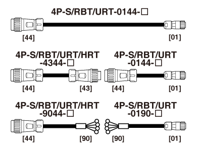
Number of divisions, resolution, and sensor cable length of the ABSOCODER sensor
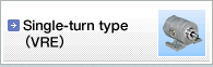
VRE Single-turn type
| Item | Specification | ||||
|---|---|---|---|---|---|
| Converter model | VS-10GH-□-1-V1R | ||||
| Applicable sensor | VRE-P061, VRE-P074, VRE-P101 | ||||
| Total number of turns | 1 | ||||
| Number of divisions | 8192(213) | ||||
| Position detection format | Absolute position detection | ||||
| Max. sensor cable length |
Standard(S) | 500m | |||
| Robotic (RBT) | 250m | ||||
| JKPEV-S (1.25mm2×5P) |
300m | ||||
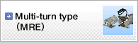
MRE Multi-turn type
| Item | Specification | ||||||
|---|---|---|---|---|---|---|---|
| Converter model | VS-10GH-□-1-M2R | ||||||
| Applicable sensor | MRE-32SP061 | MRE-G□SP061 □:Total number of turns | |||||
| Total number of turns | 32 | 64 | 128 | 160 | 256 | 320 | |
| Divisions/Turn | 4096 | 2048 | 1024 | 819.2 | 512 | 409.6 | |
| Total number of divisions | 131072(217) | ||||||
| Position detection format | Absolute position detection | ||||||
| Max. sensor cable length |
Standard(S) | 200m | 300m | ||||
| Robotic (RBT) | 100m | 150m | |||||
| JKPEV-S (1.25mm2×5P) |
200m | 300m | |||||
| Item | Specification | ||||||
|---|---|---|---|---|---|---|---|
| Converter model | VS-10GH-□-1-M2R | ||||||
| Applicable sensor | MRE-32SP074 | MRE-G□SP074 □:Total number of turns | |||||
| Total number of turns | 32 | 64 | 128 | 160 | 256 | 320 | |
| Divisions/Turn | 4096 | 2048 | 1024 | 819.2 | 512 | 409.6 | |
| Total number of divisions | 131072(217) | ||||||
| Position detection format | Absolute position detection | ||||||
| Max. sensor cable length |
Standard(S) | 300m | |||||
| Robotic (RBT) | 150m | ||||||
| JKPEV-S (1.25mm2×5P) |
300m | ||||||
| Item | Specification | |||||||||||
|---|---|---|---|---|---|---|---|---|---|---|---|---|
| Converter model | VS-10GH-□-1-M2R | |||||||||||
| Applicable sensor | MRE-32SP101 | MRE-G□SP101 □:Total number of turns | ||||||||||
| Total number of turns | 32 | 64 | 128 | 160 | 256 | 320 | 512 | 1280 | 2048 | 2560 | 3072 | |
| Divisions/Turn | 4096 | 2048 | 1024 | 819.2 | 512 | 409.6 | 256 | 102.4 | 64 | 51.2 | 42.6 | |
| Total number of divisions | 131072(217) | |||||||||||
| Position detection format | Absolute position detection | |||||||||||
| Max.sensor cable length |
Standard(S) | 300m | ||||||||||
| Robotic (RBT) | 150m | |||||||||||
| JKPEV-S (1.25mm2×5P) |
300m | |||||||||||
CYLNUC Smart Linear Position Sensing Cylinder
| Item | Specification | ||
|---|---|---|---|
| Converter model | VS-10GH-□-1-LC | ||
| Applicable sensor | CYLNUC | ||
| Absolute detection range | 12.8mm | ||
| Resolution | 1.5625μm | ||
| Position detection format | Semi - absolute position detection | ||
| Max. sensor cable length |
Standard(S) | 200m | |
| Robotic (RBT) | 100m | ||
| JKPEV-S (1.25mm2×5P) |
200m | ||
General Purpose Inrodsensor
| Item | Specification | ||
|---|---|---|---|
| Converter model | VS-10GH-□-1-LC | ||
| Applicable sensor | IRS-51.2P | ||
| Absolute detection range | 51.2mm | ||
| Resolution | 6.25μm | ||
| Position detection format | Semi - absolute position detection | ||
| Max. sensor cable length |
Standard(S) | 200m | |
| Robotic (RBT) | 100m | ||
| JKPEV-S (1.25mm2×5P) |
200m | ||
I/O spcification
| Item | VS-10GH-D-1 | VS-10GH-A-1 | VS-10GH-C-1 | Description | |
|---|---|---|---|---|---|
| Input signals |
Program No. | 8 points | 8 points | 8 points | Inputs the exteral program No. |
| Current position preset | 3 points | 3 points | 3 points | The current position value is changed to a value which is pre-designated by the external signal. | |
| External measuring trigger |
1 point | 1 point | 1 point | When this signal is input from the host controller, the Current Position Value will be held so that it can be read as a measuring value. | |
| Switch output enabling | 1 point | 1 point | 1 point | The switch signal is output when turning ON this signal. | |
| DTC input for BCD output | 1 point | - | - | Updating of the current position output will be suspended while this signal turns ON. | |
| Error cancel | 1 point | 1 point | 1 point | Cancels an error when this input is turned ON. | |
| Output signals |
Switch outputs*2 | 30 points | 30 points | 30 points | ON/OFF signal will be output based on the switch output setting values. |
| System ready | 1 point | 1 point | 1 point | Outputs when controller and sensor are functioning normally. | |
| Program No. | 8 points | 8 points | 8 points | The currently selected program No. is output. | |
| Current position value (BCD/binary) |
24 points (6-digit BCD/23-bit binary+sign) |
- | - | Outputs current position or measuring values in BCD or binary code. | |
| Decimal point | 3 points | - | - | Outputs decimal points when current position or measuring values are output in BCD code. | |
| BCD minus sign | 1 point | - | - | Outputs when negative current position or measuring values are output in BCD code. | |
| Latch pulse | 1 point | - | - | This is updating timing signal of the current position outputs. | |
| HOLD measuring completed *2 |
1 point | 1 point | 1 point | Turns ON when the HOLD measuring is completed and this current position value is held. | |
| Motion detection *2 | 1 point | 1 point | 1 point | Outputs when the detected travel direction and speed match the predetermined values. | |
| Preset error *2 | 1 point | 1 point | 1 point | Outputs when the current position preset signal is turned on in the position outside of the preset possible range. | |
*2 : It is assigned to the switch output 28 when using the HOLD measuring completed signal.
It is assigned to the switch output 29 when using the motion detection signal.
It is assigned to the switch output 30 when using the preset error signal.
Switch output and program No. connector
| Item | Input specifications | Item | Output Specifications | |||
|---|---|---|---|---|---|---|
| Input signals | Program No. Current position preset External measuring trigger Switch output enabling Error cancel |
Output signals | Program No. Switch output System ready HOLD measuring completed Motion detection Preset error |
|||
| Input circuit | DC input, photo-coupler isolation | Output circuit | Photo - coupler isolation | |||
| Rated input voltage | 12VDC | 24VDC | Rated load voltage | 12/24VDC | ||
| Rated input current | 4mA | 10mA | Load voltage range | 10.2 ~ 30VDC | ||
| Input voltage range | 10.2 ~ 30VDCV | Max. load current | 100mA | |||
| ON voltage | 10VDC or more | Current leak when OFF | 0.1mA or less | |||
| OFF voltage | 4VDC or less | Max. voltage drop when ON | 2.0V or less (at 100mA) | |||
| Response time | OFF to ON | 0.04 ms (at 24V input voltage) | Response time | OFF to ON | 1ms (at 100mA load-current resistance load) | |
| ON to OFF | 0.2ms (at 24V input voltage) | ON to OFF | 1ms (at 100mA load-current resistance load) | |||
BCD output connector
| Item | Input specifications | Item | Output Specifications | |||
|---|---|---|---|---|---|---|
| Input signals | DTC input for BCD output | Output signals | Current position value (BCD / binary) Decimal point BCD minus sign Latch pulse |
|||
| Input circuit | DC input, photo-coupler isolation | Output circuit | Photo-coupler isolation | |||
| Rated input voltage | 12VDC | 24VDC | Rated load voltage | 12/24VDC | ||
| Rated input current | 4mA | 10mA | Load voltage range | 10.2 ~ 30VDC | ||
| Input voltage range | 10.2 ~ 30VDC | Max. load current | 20mA 100mA (latch pulse only) |
|||
| ON voltage | 10VDC or more | Current leak when OFF | 0.1mA or less | |||
| OFF voltage | 4VDC or less | Max. voltage drop when ON | 1.5V or less (at 20mA) 1.5V or less (at 100mA)(latch pulse only) |
|||
| Response time | OFF to ON | 0.04 ms (at 24V input voltage) | Response time | OFF to ON | 1ms (at 100mA load-current resistance load) | |
| ON to OFF | 0.2ms (at 24V input voltage) | ON to OFF | 1ms (at 100mA load-current resistance load) | |||
Analog output connector
Position/Speed Voltage Output
| Item | Specification |
|---|---|
| Output voltage | VS-10B Mode: 0 ~ 10VDC or −10 ~ +10VDC Extended mode: −10 ~ +10VDC Position/Speed and voltage can be set as required at the parameter. |
| External load resistance | 1kΩ〜1MΩ |
| Output voltage resolution | 0.3051 mV (−10V ~ +10V / 65536 divisions) |
| Output voltage accuracy | 100mV (0 ~ +55℃) |
| Analog response time | Max. 100µs (Switching between 10V and 0V) |
| Sampling time | 1ms |
| Isolation format | Insulated between control and output circuits |
Position/Speed Current Output
| Item | Specification |
|---|---|
| Output current | 4 ~ 20mADC Position/Speed data for 4mADC and Position/Speed data for 20mADC can be set as required at the parameter. |
| External load resistance | 510Ω or less |
| Output current resolution | 0.24µA (4mA to 20mA / 65536 divisions) |
| Output current accuracy | 200µA (0 ~ +55℃) |
| Analog response time | Max. 100µs (Switching between 20mA and 4mA) |
| Sampling time | 1ms |
| Isolation format | Insulated between control and output circuits. |
Dimensions
 VS-10GH-D-1
- VS-10GH-A-1
- VS-10GH-C-1
Application Introduction


- Principle of ABSOCODER
- Full Line-Up of ABSOCODER
- Converter
- VARICAM®
- VARILIMIT®
- PLC Module Converter
- Network Solution Controller
- Network Solution Controller 2
- Positioning output controller
- Heavy Duty Converter
- Heavy Duty ABSO PULPUL®
- Heavy Duty NP-SCALE
- Heavy Duty VARILIMIT®
- Heavy Duty PLC Module Converter
- Heavy Duty Network Solution Controller
- Heady Duty Solutions
- Single Turn Rotary Position Sensor
- Multi Turn Rotary Position Sensor
- Linear Position Sensor
- Smart Linear Position Sensing Cylinder
- ABSOCODER Built-In Sensing Products
- Extension Sensor Cable
- ezABSO® Pulse Series
- ezABSO® Network Series
- ezABSO® Network Series
CC-Link IE TSN - Magnetic Proximity Sensor
- Tension Measurement
- Eddy Current Displacement Sensor
- Explosion Proof Solution
- Joint Development Products
- Slip-Ring and Wireless Transfer Device
- Renewal Solution
- Customized NSD Solution
- Parameter Software


 Explore a Career at NSD
- Work With NSD
 Global Network
- NSD is where the customer needs are
 Principle of ABSOCODER
- Please check the creative principle of NSD ABSOCODER
 NSD HISTORY
- Preparation for a better future and for the next generation
 Major Application
- Please check the wide-use ABSOCODER's application
 Extension Sensor Cable
- Please check the extension sensor cable for ABSOCODER
 NSD YouTube Channel
- Please check the NSD official YouTube channel
 ON-LINE EXHIBITION
- Introducing the NSD on-line exhibition
 ON-LINE MEETING
- NSD on-line meeting service page