Heavy Duty PLC Module Converter
Description
NSD smart PLC built-in converters provide an extremely reliable performance and present a variety of options to the customer under harsh environment operation.
![]()
![]()
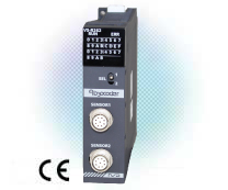
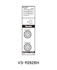
VS-R262BH
VS-R262BH is Binary Code output NSD heavy duty smart PLC built-in controller for MELSEC iQ-R series PLC.
Download the profile (CSP+) for MELSEC iQ-R from the download page (Open Network Definition File).
- Model coding
- Applicable System
- ABSOCODER Basic Configuration
- Specification
- Dimensions
- Application Introduction
Model coding
VS-R262BH-[1]
- [1]Applicable sensor
-
Code Applicable sensor V1R VRE-P061/074/101 M2R MRE-32SP061/074/101,MRE-G□SP061/074/101 LC CYLNUC,Inrodsensor(IRS-51.2P, IRS-32.8P) L8 VLS-8SM
Applicable System
-
Programmable
controller CPUR00CPU R01CPU R02CPU R04CPU R08CPU R16CPU R32CPU R120CPU Programmable
controller CPU
(CC-Link IE embedded)R04ENCPU R08ENCPU R16ENCPU R32ENCPU R120ENCPU Process CPU *1 R08PCPU R16PCPU R32PCPU R120PCPU Safety CPU *2 R08SFCPU R16SFCPU R32SFCPU R120SFCPU C Controller *3 R12CCPU-V CC-Link IE Field
Network
remote head moduleRJ72GF15-T2 MELSEC MX
Controller
MX-R modelMXR300-16 MXR300-32 MXR300-64 MXR300-128 MXR300-256 *1: When using the redundant mode, the redundant extension base unit (R68WRB) should be used.
For details of the redundant extension base unit, refer to the following manual.
- MELSEC iQ-R Module Configuration Manual (SH081262)
The inter-module synchronization function is not available when our unit is mounted on the redundant extension base unit.
*2: Some functions are not supported by CPU. For details of the unsupported functions, refer to the following manual.
- MELSEC iQ-R CPU Module User's Manual (Startup) (SH081263)
- MELSEC iQ-R CPU Module User's Manual (Application) (SH081264)
*3: Our CSP+ files cannot be used with the CW Configurator (engineering software) manufactured by Mitsubishi Electric Corporation.
When specifying our module in the CW Configurator, select [Add New Module] from "Module Information" in the Navigation Window, and then select "Base Mounted Type General Module" ⇒ "Gen. Intelligent Module (1 slot)".
ABSOCODER Basic Configuration


Specification
General specification
| Item | Specifications | |||||
|---|---|---|---|---|---|---|
| Operating ambient temperature |
0 to 55℃ (When an extended temperature range base unit is not used) | |||||
| 0 to 60℃ (When an extended temperature range base unit is used) | ||||||
| Storage ambient temperature |
-25 to 75℃ | |||||
| Operating ambient humidity |
5 to 95%RH, non-condensing | |||||
| Storage ambient humidity |
5 to 95%RH, non-condensing | |||||
| Vibration resistance | Compliant with JIS B 3502 and IEC 61131-2 |
- | Frequency | Constant acceleration |
Half amplitude | Sweep count |
| Under intermittent vibration |
5 to 8.4Hz | - | 3.5mm | 10 times each in X, Y, Z directions |
||
| 8.4 to 150Hz | 9.8m/s2 | - | ||||
| Under continuous vibration |
5 to 8.4Hz | - | 1.75mm | - | ||
| 8.4 to 150Hz | 4.9m/s2 | - | ||||
| Shock resistance | Compliant with JIS B 3502 and IEC 61131-2 (147 m/s2, 3 times each in X, Y, and Z bidirections) | |||||
| Operating atmosphere | No corrosive gases, flammable gases, less conductive dust | |||||
| Operating altitude | 0 to 2000m | |||||
| Installation location | Inside a control panel | |||||
| Overvoltage category | II or less | |||||
| Pollution degree | 2 or less | |||||
| Internal power consumption |
0.7 A (5 VDC) | |||||
| Mass | 0.2kg | |||||
Performance Specification
| Item | Specification | ||||
|---|---|---|---|---|---|
| Converter model | VS-R262BH-V1R | VS-R262BH-M2R | |||
| Applicable sensor | VRE-P061 VRE-P074 VRE-P101 |
MRE-32SP061 | MRE-G□SP061 MRE-32SP074 MRE-G□SP074 |
MRE-32SP101 MRE-G□SP101 |
|
| Position detection format | Absolute position detection | ||||
| Number of divisions | 8192 Divisions×1 Turn | 4096 Divisions×32 Turns 〜 409.6 Divisions×320 Turns |
4096 Divisions×32 Turns 〜 42.6 Divisions×3072 Turns |
||
| Number of detection axes | 2 | ||||
| Data setting method | PLC CPU program | ||||
| Position data sampling time |
0.1ms | ||||
| Number of I/O points occupied | 32 points (I/O assignment: intelligent) | ||||
| Setting value memory | Non-volatile memories | ||||
| Auxiliary functions | Current position detection, current position value setting | ||||
| Max. sensor cable length |
Standard(S) | 500m | 200m | 300m | |
| Robotic(RBT) | 250m | 100m | 150m | ||
| JKPEV-S (1.25mm2×5P) |
300m | 200m | 300m | ||
| Item | Specification | ||||
|---|---|---|---|---|---|
| Converter model | VS-R262BH-LC | VS-R262BH-L8 | |||
| Applicable sensor | CYLNUC | IRS-51.2 | IRS-32.8 | VLS-8SM | |
| Position detection format | Semi - Absolute position detection | ||||
| Resolution | 1.5625μm (12.8mm/8192 Divisions) |
6.25μm (51.2mm/8192 Divisions) |
4μm (32.8mm/8192 Divisions) |
1μm (8.192mm/8192 Divisions) |
|
| Number of detection axes | 2 | ||||
| Data setting method | PLC CPU program | ||||
| Position data sampling time |
0.1ms | ||||
| Number of I/O points occupied | 32 points (I/O assignment: intelligent) | ||||
| Setting value memory | Non-volatile memories | ||||
| Auxiliary functions | Current position detection, current position value setting | ||||
| Max. sensor cable length |
Standard(S) | 200m | 200m | ||
| Robotic(RBT) | 100m | 100m | |||
| JKPEV-S (1.25mm2×5P) |
200m | - | |||
Dimensions
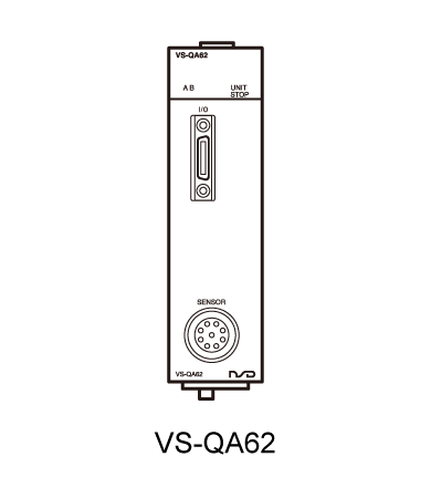
VS-QA62
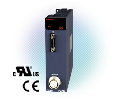
VS-QA62 is NSD smart PLC built-in controller for MELSEC-Q series PLC of Mitsubishi which is directly installed in PLC module without any wiring. VS-QA62 provides system motion control with limit switches output and all the parameters can be set by NSD programming software with your PC.
- Model coding
- Applicable System
- ABSOCODER Basic Configuration
- Specification
- Dimensions
- Application Introduction
Model coding
VS-QA62-[1]
- [1]Applicable sensor
-
Code Applicable sensor M2R MRE-32SP061/074/101,MRE-G□SP061/074/101
Applicable System
-
Programmable
controller
CPUQ00JCPU Q00CPU Q01CPU Q02CPU Q02HCPU Q06HCPU Q12HCPU Q25HCPU Q02PHCPU Q06PHCPU Q12PHCPU Q25PHCPU Q04UDPVCPU Q06UDPVCPU Q13UDPVCPU Q26UDPVCPU Q12PRHCPU Q25PRHCPU Q00UJCPU Q00UCPU Q01UCPU Q02UCPU Q03UDCPU Q04UDHCPU Q06UDHCPU Q10UDHCPU Q13UDHCPU Q20UDHCPU Q26UDHCPU Q03UDECPU Q04UDEHCPU Q06UDEHCPU Q10UDEHCPU Q13UDEHCPU Q20UDEHCPU Q26UDEHCPU Q50UDEHCPU Q100UDEHCPU Q03UDVCPU Q04UDVCPU Q06UDVCPU Q13UDVCPU Q26UDVCPU Q06CCPU-V Q06CCPU-V-B Q12DCCPU-V Q24DHCCPU-V Q24DHCCPU-LS Q01WCPU-W1-J Q01WCPU-W1-CF-J Q01WCPU-W1-E Q01WCPU-W1-CF-E PPC-100-DC5511 PPC-100-DC5311 Remoto
I/O moduleQJ72LP25-25 QJ72LP25G QJ72BR15 Click here for more information.
ABSOCODER Basic Configuration
Specification
General specification
| Item | Specifications | |||||
|---|---|---|---|---|---|---|
| Operating ambient temperature |
0 to 55℃ | |||||
| Storage ambient temperature |
-25 to 75℃ | |||||
| Operating ambient humidity |
5 to 95%RH, non-condensing | |||||
| Storage ambient humidity |
||||||
| Vibration resistance | Compliant with JIS B 3502 and IEC 61131-2 |
- | Frequency | Constant acceleration |
Half amplitude | Sweep count |
| Under intermittent vibration |
5 to 8.4Hz | - | 3.5mm | 10 times each in X, Y, Z directions |
||
| 8.4 to 150Hz | 9.8m/s2 | - | ||||
| Under continuous vibration |
5 to 8.4Hz | - | 1.75mm | - | ||
| 8.4 to 150Hz | 4.9m/s2 | - | ||||
| Shock resistance | Compliant with JIS B 3502 and IEC 61131-2 (147 m/s2, 3 times each in 3 directions X, Y, Z) | |||||
| Operating atmosphere | No corrosive gases | |||||
| Operating altitude | 0 to 2000m | |||||
| Installation location | Inside a control panel | |||||
| Overvoltage category | II or less | |||||
| Pollution degree | 2 or less | |||||
| Equipment class | Class I | |||||
| Internal power consumption |
0.7 A (5 VDC) | |||||
| Mass | 0.2kg | |||||
Performance Specification
| Item | Specification | |||||
|---|---|---|---|---|---|---|
| Converter model | VS-QA62-M2R | |||||
| Applicable sensor | MRE-32SP061 | MRE-G□SP061 MRE-32SP074 MRE-G□SP074 |
MRE-32SP101 MRE-G□SP101 |
|||
| Position detection format | Absolute position detection | |||||
| Total number of divisions (Resolution) | 131072 Divisions (4096 Divisions×32 Turns ~ 409.6 Divisions×320 Turns) |
131072 Divisions (4096 Divisions×32 Turns ~ 42.6 Divisions×3072 Turns) |
||||
| Number of detection axes | 1 | |||||
| Data setting method | PLC CPU program | |||||
| For limit switch output function |
Number of programs | 1 | ||||
| Number of multi-dogs | 5-dog/CH. | |||||
| Number of output channels |
Function selection / Output destination |
For limit switch output function |
For positioning function | |||
| I/O output | 8 CH. | 0 CH. | ||||
| Device X | 8 CH. | 0 CH. | ||||
| Buffer memory | 16 CH. | 16 CH. | ||||
| Positioning function (speed switching control) |
Control format | Unidirectional positioning or bidirectional positioning | ||||
| Target position setting method |
1-point setting prior to positioning operation by the sequence program | |||||
| Max. number of positioning points |
1-point | |||||
| Number of registered positioning pattern data |
2 | |||||
| Number of channels for positioning signal output |
8CH. FWD, RVS, High-speed, Low-speed, Brake release, In-position, Positioning in progress, Operation error |
|||||
| Positioning function (acceleration/decel eration control) |
Control format | Unidirectional positioning or bidirectional positioning | ||||
| Target position setting method |
1-point setting prior to positioning operation by the sequence program | |||||
| Max. number of positioning points |
1-point | |||||
| Number of channels for positioning signal output |
7CH. FWD, RVS, Brake release, In-position, Positioning in progress, Operation error, Speed command |
|||||
| Number of registered positioning pattern data |
1 | |||||
| Current position setting function | Initial setting, Current position preset | |||||
| JOG operation function | JOG operation executed by FWD JOG/RVS JOG signal inputs | |||||
| Pulse output count | 1~131072pulse | |||||
| Sampling time (Response time) |
Limit switch output signal Positioning output signal |
0.4ms(0.8ms) | ||||
| Current position output | 0.2ms(0.4ms) | |||||
| Gate time | Speed output | 0.8ms, 1.6ms, 3.2ms, 6.4ms, 12.8ms, 25.6ms, 51.2ms Able to select by parameter setting |
||||
| Rotation speed output | 117ms | |||||
| Travel speed output | 200ms | |||||
| Number of I/O points occupied | 32 points (I/O assignment: intelligent) | |||||
| Setting value memory | Non-volatile memories | |||||
| Max. sensor cable length |
Standard(S) | 200m | 300m | |||
| Robotic (RBT) | 100m | 150m | ||||
| JKPEV-S (1.25mm2×5P) |
200m | 300m | ||||
I/O spcification
| Item | Specification | |||
|---|---|---|---|---|
| Input | Input signals | Current position preset input 2 points | ||
| Input circuit | DC input, photo-coupler isolation | |||
| Rated input voltage | 12VDC | 24VDC | ||
| Rated input current | 3mA | 6.5mA | ||
| Voltage range to be used | 10.2 ~ 30VDC | |||
| ON voltage | 10VDC or more | |||
| OFF voltage | 2VDC or less | |||
| Common connections | 1 common for 2 points (common terminal: 11, 12) | |||
| Output | Output signals |
For current position detection only |
No outpt | |
| For switch output function only |
Switch output 8 points | |||
| For switch output & positioning functions |
Switch output 0 point Positioning output 8 points |
|||
| Output circuit | Photo-coupler isolation | |||
| Rated load voltage | 12/24VDC | |||
| Load voltage range | 10.2 ~ 30VDC | |||
| Max. load current | 50mA | |||
| Max. voltage drop when ON | 2.0V or less at 50mA, 1.7V or less at 10mA | |||
| Common connections | 1 common for 8 points (common terminal: 24, 25) | |||
| Pulse Output |
Output signals | A+/A-、B+/B- | ||
| Output circuit | Line driver output (equivalent to AM26C31C) | |||
| Max. load current | ±20mA max./1point | |||
| Differential output voltage | 2.0V or more (Io=20mA) | |||
| Isolation format | Photo-coupler isolation | |||
| Min. load resistance | 100Ω min. | |||
| External power supply *1 | 0.2 A(5VDC : 4.75 to 5.25VDC) | |||
| Max. frequency | 100 kHz | |||
| Analog Output |
Output signals | Analog+ / Analog- | ||
| Isolation method | Photo-coupler isolation | |||
| Output voltage range | -10V to +10VDC | |||
| Output voltage resolution | 0.3051mV (-10V to +10V / 65536 divisions) | |||
| Updating cycle | 0.4ms | |||
| External cable connection format | 26-points connector | |||
- *1 : Pulse output circuits require the external supply voltage (5 VDC).
Dimensions
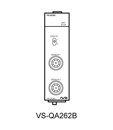
VS-QA262B
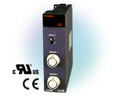
VS-QA262B is NSD heavy duty smart PLC built-in controller for MELSEC-Q series with 2 sensor channels.
- Model coding
- Applicable System
- ABSOCODER Basic Configuration
- Specification
- Dimensions
- Application Introduction
Model coding
VS-QA262B-[1]
- [1]Applicable sensor
-
Code Applicable sensor V1R VRE-P061/074/101 V2 VRE-16TS100 M2R MRE-32SP061/074/101,MRE-G□SP061/074/101 LC CYLNUC,Inrodsensor(IRS-51.2P) L8 VLS-8SM
Applicable System
-
Programmable
controller
CPUQ00JCPU Q00CPU Q01CPU Q02CPU Q02HCPU Q06HCPU Q12HCPU Q25HCPU Q02PHCPU Q06PHCPU Q12PHCPU Q25PHCPU Q04UDPVCPU Q06UDPVCPU Q13UDPVCPU Q26UDPVCPU Q12PRHCPU Q25PRHCPU Q00UJCPU Q00UCPU Q01UCPU Q02UCPU Q03UDCPU Q04UDHCPU Q06UDHCPU Q10UDHCPU Q13UDHCPU Q20UDHCPU Q26UDHCPU Q03UDECPU Q04UDEHCPU Q06UDEHCPU Q10UDEHCPU Q13UDEHCPU Q20UDEHCPU Q26UDEHCPU Q50UDEHCPU Q100UDEHCPU Q03UDVCPU Q04UDVCPU Q06UDVCPU Q13UDVCPU Q26UDVCPU Q06CCPU-V Q06CCPU-V-B Q12DCCPU-V Q24DHCCPU-V Q24DHCCPU-LS Q01WCPU-W1-J Q01WCPU-W1-CF-J Q01WCPU-W1-E Q01WCPU-W1-CF-E PPC-100-DC5511 PPC-100-DC5311 Remoto
I/O moduleQJ72LP25-25 QJ72LP25G QJ72BR15 Click here for more information.
ABSOCODER Basic Configuration


Specification
General specification
| Item | Specifications | |||||
|---|---|---|---|---|---|---|
| Operating ambient temperature |
0 to 55℃ | |||||
| Storage ambient temperature |
-25 to 75℃ | |||||
| Operating ambient humidity |
5 to 95%RH, non-condensing | |||||
| Storage ambient humidity |
||||||
| Vibration resistance | Compliant with JIS B 3502 and IEC 61131-2 |
- | Frequency | Constant acceleration |
Half amplitude | Sweep count |
| Under intermittent vibration |
5 to 8.4Hz | - | 3.5mm | 10 times each in X, Y, Z directions |
||
| 8.4 to 150Hz | 9.8m/s2 | - | ||||
| Under continuous vibration |
5 to 8.4Hz | - | 1.75mm | - | ||
| 8.4 to 150Hz | 4.9m/s2 | - | ||||
| Shock resistance | Compliant with JIS B 3502 and IEC 61131-2 (147 m/s2, 3 times each in 3 directions X, Y, Z) | |||||
| Operating atmosphere | No corrosive gases | |||||
| Operating altitude | 0 to 2000m | |||||
| Installation location | Inside a control panel | |||||
| Overvoltage category | II or less | |||||
| Pollution degree | 2 or less | |||||
| Equipment class | Class I | |||||
| Internal power consumption |
0.7 A (5 VDC) | |||||
| Mass | 0.2kg | |||||
Performance Specification
| Item | Specification | |||||
|---|---|---|---|---|---|---|
| Converter model | VS-QA262B-V1R | VS-QA262B-V2 | VS-QA262B-M2R | |||
| Applicable sensor | VRE-P061 VRE-P074 VRE-P101 |
VRE-16TS100 | MRE-32SP061 | MRE-G□SP061 MRE-32SP074 MRE-G□SP074 |
MRE-32SP101 MRE-G□SP101 |
|
| Position detection format | Absolute position detection | |||||
| Number of divisions | 8192 Divisions×1 Turn | 65536 Divisions×1 Turn | 4096 Divisions×32 Turns 〜 409.6 Divisions×320 Turns |
4096 Divisions×32 Turns 〜 42.6 Divisions×3072 Turns |
||
| Number of detection axes | 2 | |||||
| Data setting method | PLC CPU program | |||||
| Position data sampling time |
0.4ms | |||||
| Response time | 0.8ms | |||||
| Number of I/O points occupied |
32 points (I/O assignment: intelligent) | |||||
| Setting value memory | Non-volatile memories | |||||
| Auxiliary functions | Current position detection, current position value setting | |||||
| Max. sensor cable length |
Standard(S) | 500m | 200m | 200m | 300m | |
| Robotic (RBT) | 250m | 100m | 100m | 150m | ||
| JKPEV-S (1.25mm2×5P) |
300m | - | 200m | 300m | ||
| Item | Specification | ||
|---|---|---|---|
| Converter model | VS-QA262B-LC | ||
| Applicable sensor | CYLNUC | IRS-51.2 | |
| Position detection format | Semi - Absolute position detection | ||
| Number of divisions | 12.8mm/8192 Divisions | 51.2mm/8192 Divisions | |
| Number of detection axes | 2 | ||
| Data setting method | PLC CPU program | ||
| Position data sampling time |
0.4ms | ||
| Response time | 0.8ms | ||
| Number of I/O points occupied |
32 points (I/O assignment: intelligent) | ||
| Setting value memory | Non-volatile memories | ||
| Auxiliary functions | Current position detection, current position value setting | ||
| Max. sensor cable length |
Standard(S) | 200m | |
| Robotic (RBT) | 100m | ||
| JKPEV-S (1.25mm2×5P) |
200m | ||
| Item | Specification | |
|---|---|---|
| Converter model | VS-QA262B-L8 | |
| Applicable sensor | VLS-8SM | |
| Position detection format | Semi - Absolute position detection | |
| Number of divisions | 8.192mm/8192 Divisions | |
| Number of detection axes | 2 | |
| Data setting method | PLC CPU program | |
| Position data sampling time |
0.4ms | |
| Response time | 0.8ms | |
| Number of I/O points occupied |
32 points (I/O assignment: intelligent) | |
| Setting value memory | Non-volatile memories | |
| Auxiliary functions | Current position detection, current position value setting | |
| Max. sensor cable length |
Standard(S) | 200m |
| Robotic (RBT) | 100m | |
| JKPEV-S (1.25mm2×5P) |
- | |
Dimensions
Application Introduction


- Principle of ABSOCODER
- Full Line-Up of ABSOCODER
- Converter
- VARICAM®
- VARILIMIT®
- PLC Module Converter
- Network Solution Controller
- Network Solution Controller 2
- Positioning output controller
- Heavy Duty Converter
- Heavy Duty ABSO PULPUL®
- Heavy Duty NP-SCALE
- Heavy Duty VARILIMIT®
- Heavy Duty PLC Module Converter
- Heavy Duty Network Solution Controller
- Heady Duty Solutions
- Single Turn Rotary Position Sensor
- Multi Turn Rotary Position Sensor
- Linear Position Sensor
- Smart Linear Position Sensing Cylinder
- ABSOCODER Built-In Sensing Products
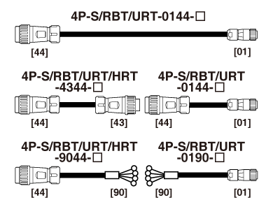
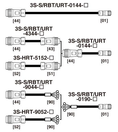
- Extension Sensor Cable
- ezABSO® Pulse Series
- ezABSO® Network Series
- ezABSO® Network Series
CC-Link IE TSN - Magnetic Proximity Sensor
- Tension Measurement
- Eddy Current Displacement Sensor
- Explosion Proof Solution
- Joint Development Products
- Slip-Ring and Wireless Transfer Device
- Renewal Solution
- Customized NSD Solution
- Parameter Software


 Explore a Career at NSD
- Work With NSD
 Global Network
- NSD is where the customer needs are
 Principle of ABSOCODER
- Please check the creative principle of NSD ABSOCODER
 NSD HISTORY
- Preparation for a better future and for the next generation
 Major Application
- Please check the wide-use ABSOCODER's application
 Extension Sensor Cable
- Please check the extension sensor cable for ABSOCODER
 NSD YouTube Channel
- Please check the NSD official YouTube channel
 ON-LINE EXHIBITION
- Introducing the NSD on-line exhibition
 ON-LINE MEETING
- NSD on-line meeting service page